I recently upgraded my mother board to one that included a connector for Front Panel Audio.
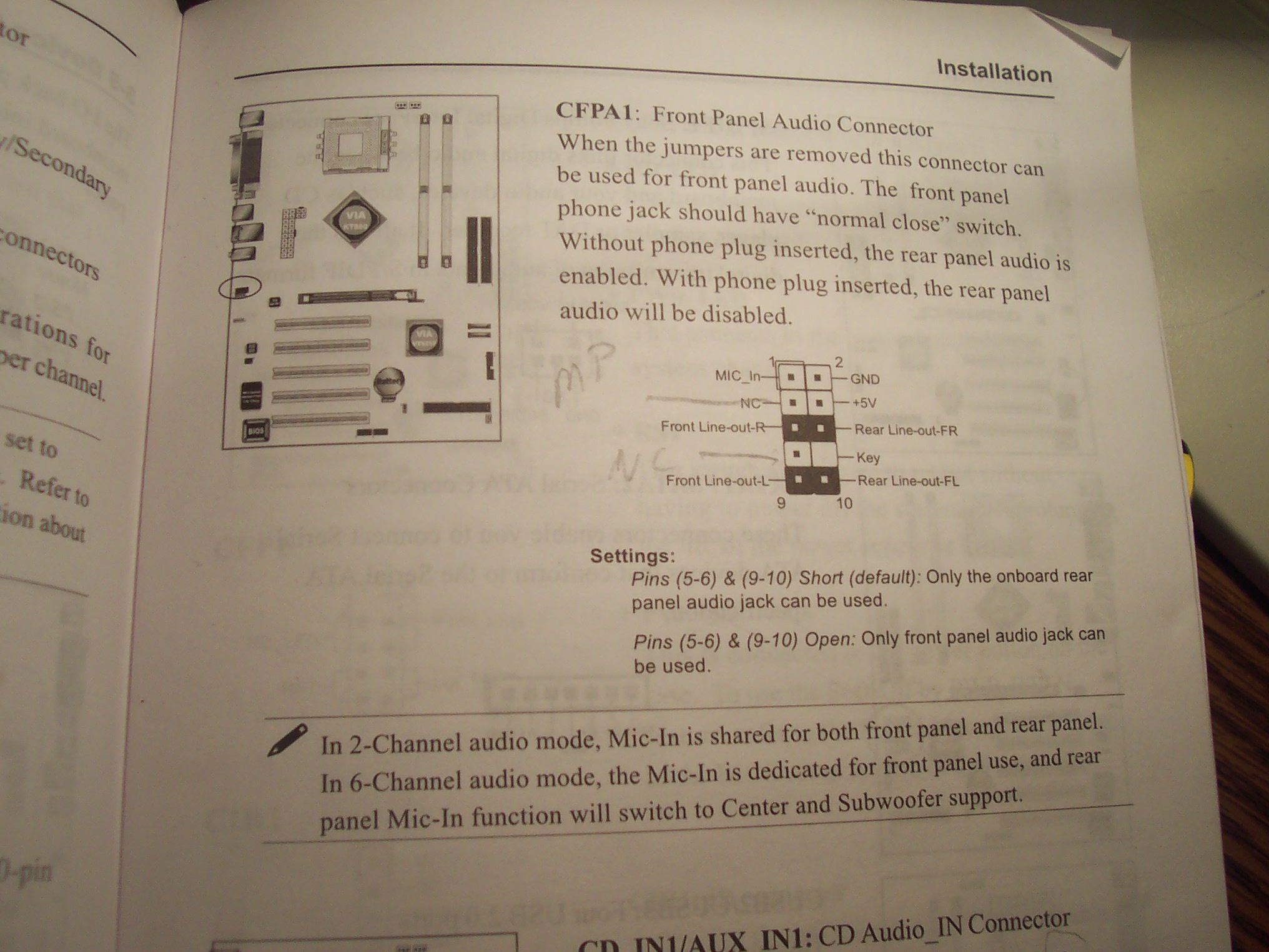
Here’s what’s shown in the manual:
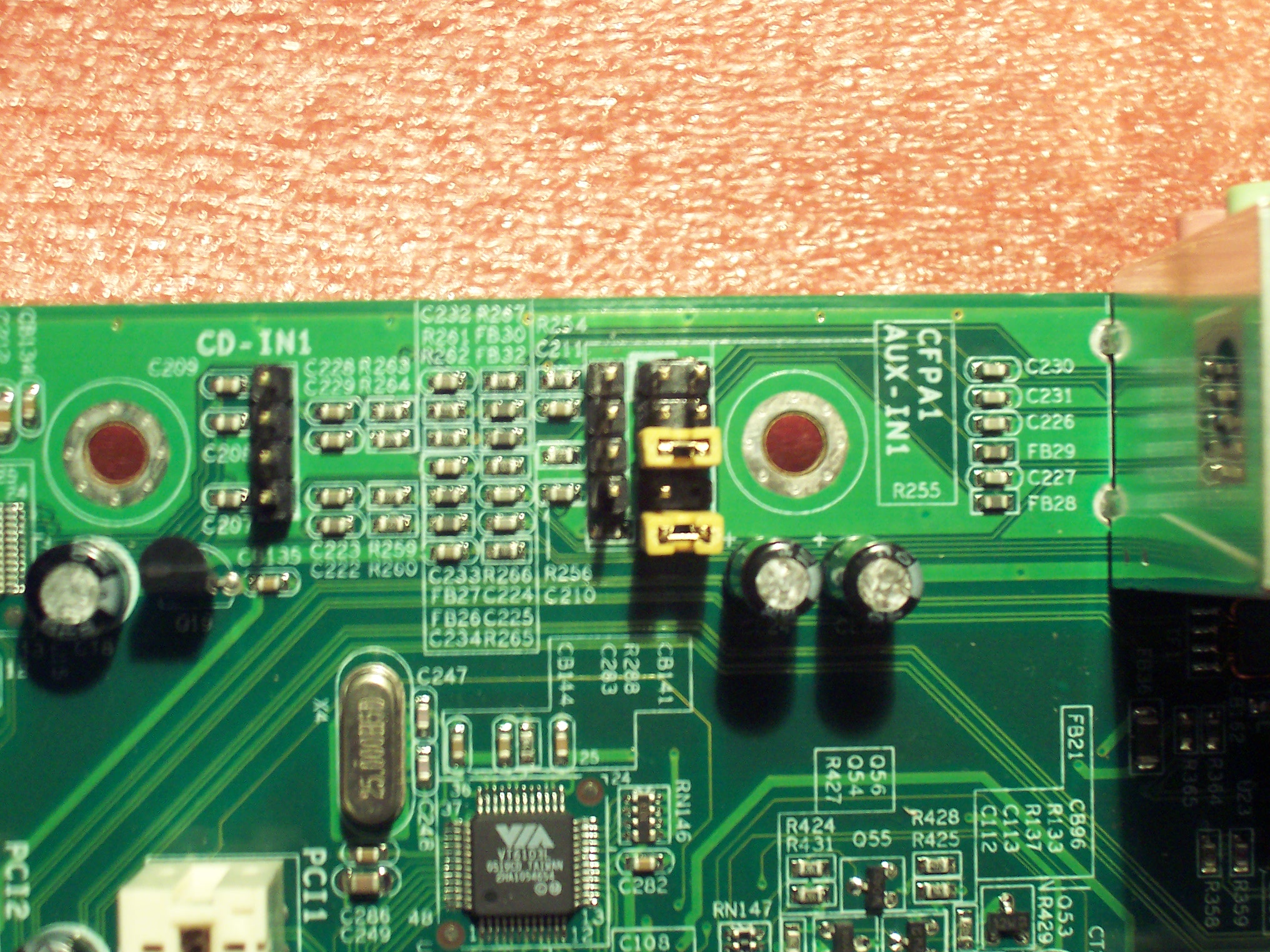
Which luckily matched up nicely with what I saw on the motherboard:
I’ve decided that these front panel audio connectors are fairly standard. AND I think my manual has the FPA jack a little mislabeled.

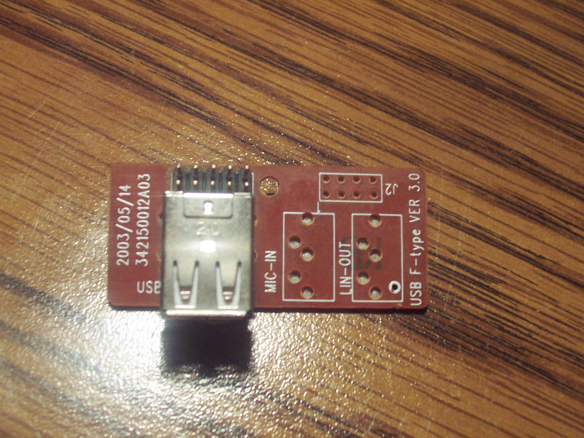
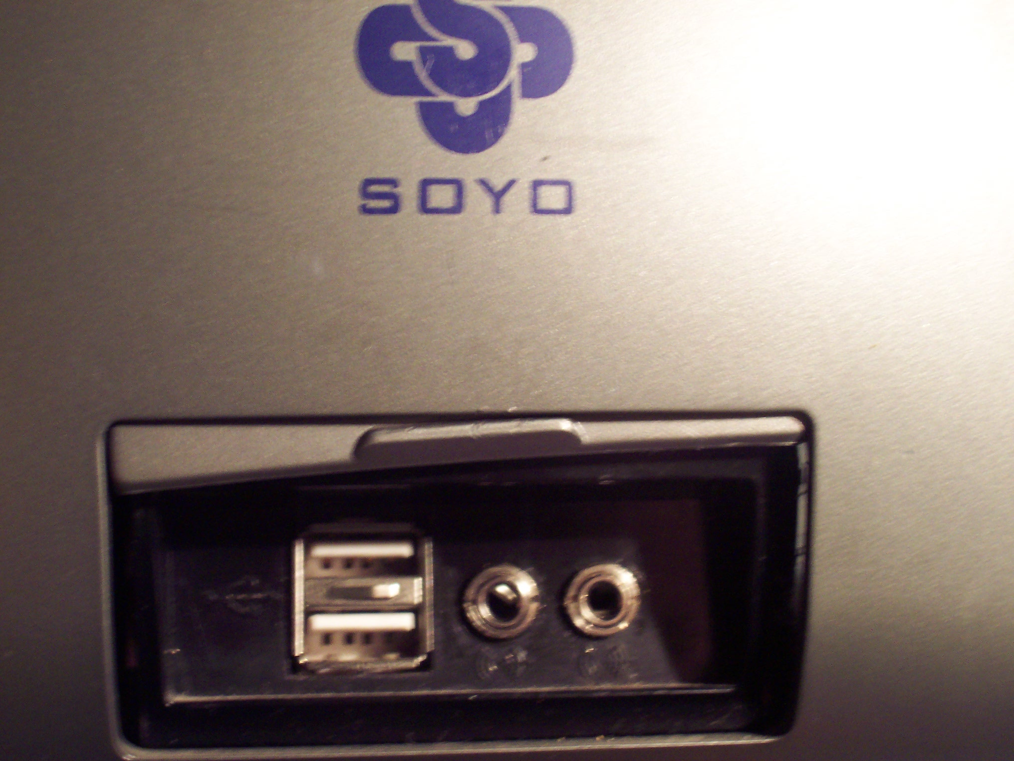
My old motherboard did not support this. And in my case (Ha!), the case didn’t either. Though the case had holes for a stereo jack, the circuitry was missing the appropriate jacks:
Now, the manual told me that it required Normally Closed jacks, which I happed to know Radio Shack carries. They are part number 274-0246.
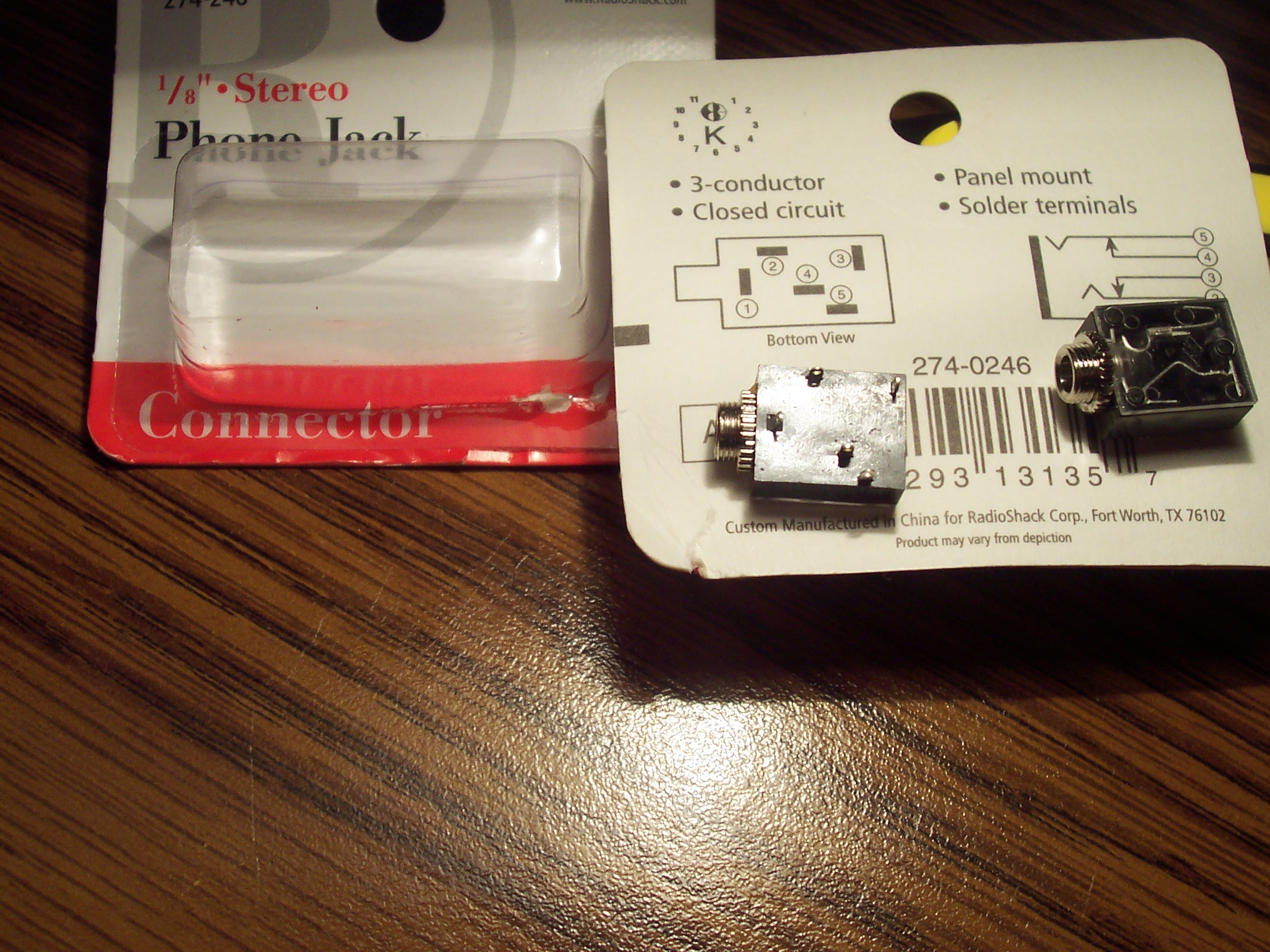
I’d used them previously when repairing the stereo jack on my Toshiba E740 PDA. Now THAT was an ugly repair. These jacks did not fit in to the case, so the poor PDA had 3 wires dangling out of its normal audio port. It extended the life of the PDA by 6 months though. Then it started having battery life issues. But that’s all another story.
A normally closed circuit allows one connection to be made when the audio jack is plugged in and another to be made when the jack is unplugged. If you look closely in this picture, you can see that in action…

So, now it was up to me to figure out how to wire all this up. I always say that people who say they can’t use computers are just intimidated by them. There’s really nothing to them if you just forge ahead.
Well, this level of wiring is out of my comfort zone and I am indeed intimidated by it. So it took me way longer than it should have to write all this down, but in the end, I think I got it.
So, I looked again at the manual to see what the jumpers connected by default. That should match the connections I want to have when the audio jack is disconnected.
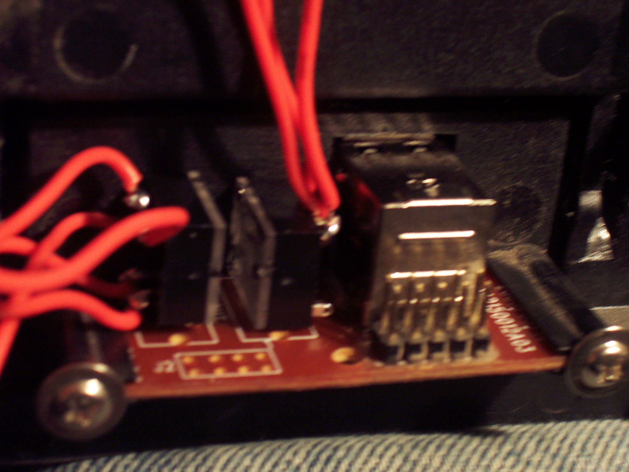
Then I looked at the back of the circuit board…
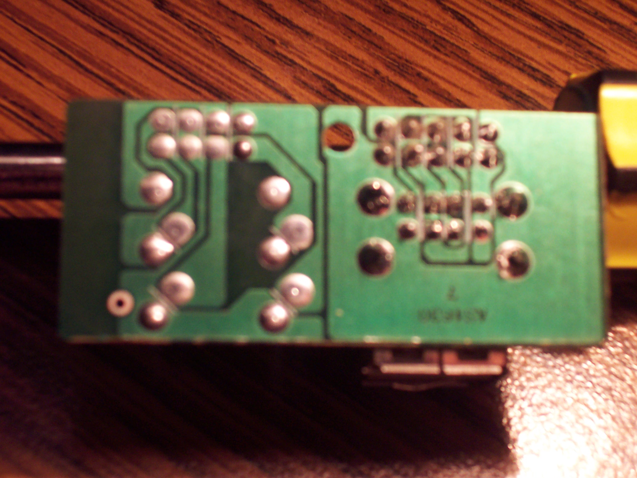
And got totally confused and lost and followed a lot of dead ends. I eventually decided that the circuit board really gave me no information. They audio jack pin layout was totally different from the one on the radio shack stereo jacks and the order of the pins holes where the audio jack would plug in did not have to match the order of what was on the motherboard.
So, I scrapped that and decided I needed a mapping of how I wanted the wires when my headphones were connected and when they were disconnected.
This is what I came up with:
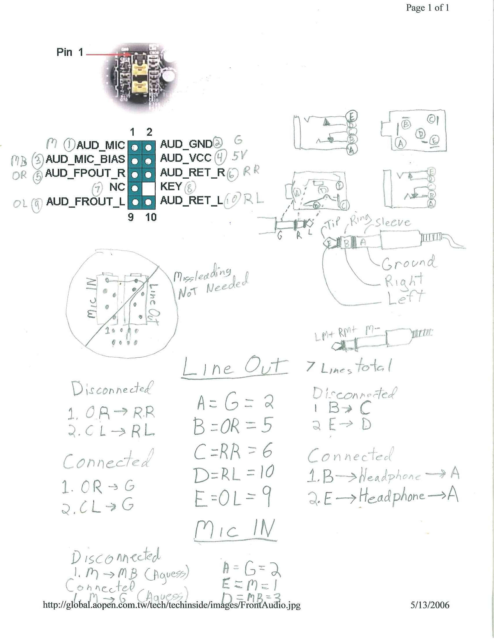
LEGEND:
OR = Output Right
RR = Return Right
OL = Output Left
RL = Return Left
G = Ground
M = Mic (In)
M = Mic Bias
I also had to figure out the parts and purposes of the 1/8 jack, the tip, the Ring and the sleeve and what was Left, Right and Ground for a stereo 1/8″ plug and for a 1/8″ mic mono plug.
That was kind of enlightening, because it now makes sense why plugging a stereo plug into a mono jack produces sound only on the right speaker… It’s because the very end is the left channel.
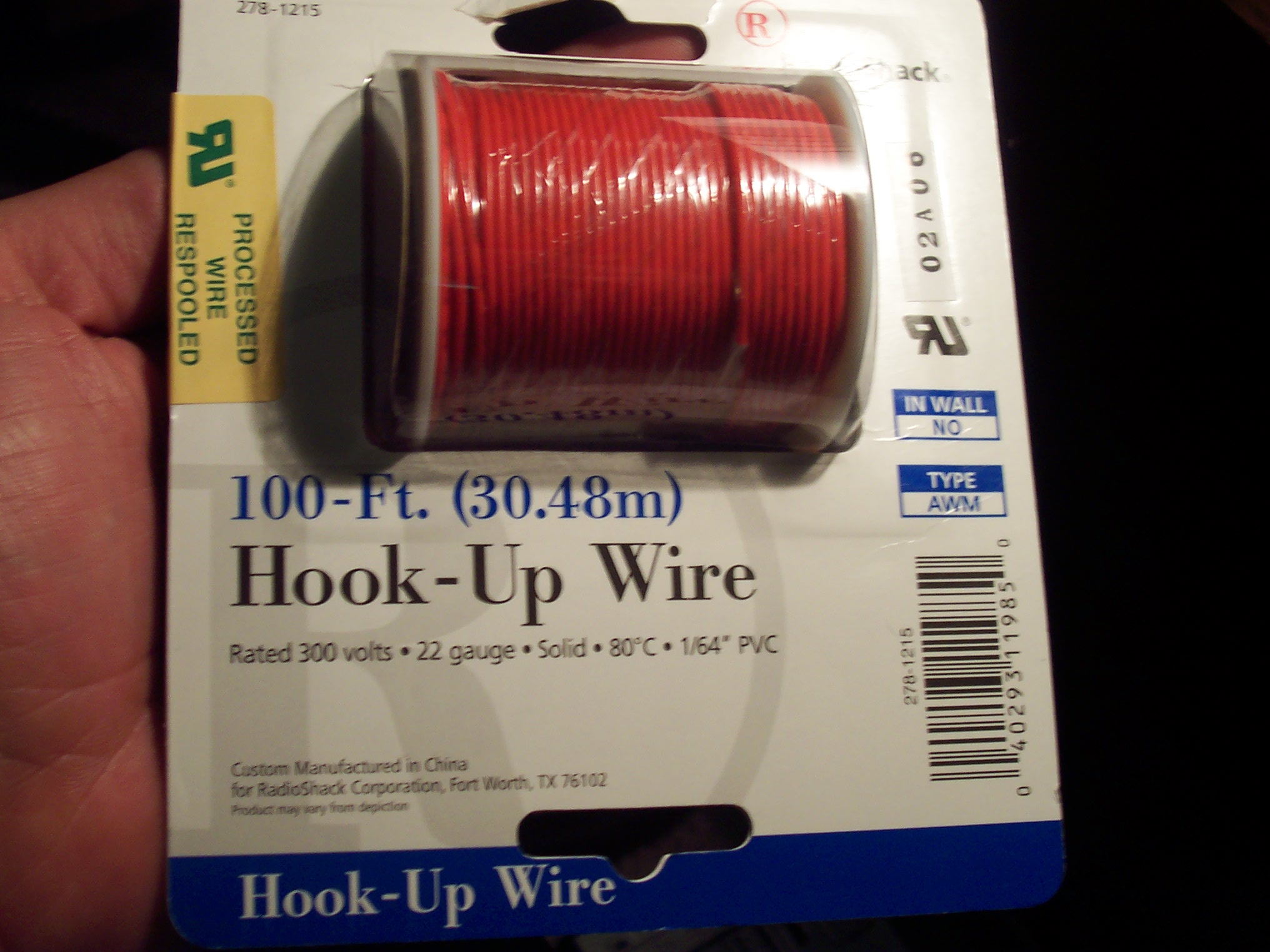
So, with all of that in hand, it’s time for wiring, I decided to get Radio Shack’s 22 gauge solid core wire. The reason that I wanted this is that I was planning on using all of the old CD player to sound card connection wires that I had lying around to make the actual connections. That solid wire fits snuggly into the little jacks at the end of the CD Audio cables. And since these are audio connecters, the impedance should be correct..
Here is the wire I’d chosen:
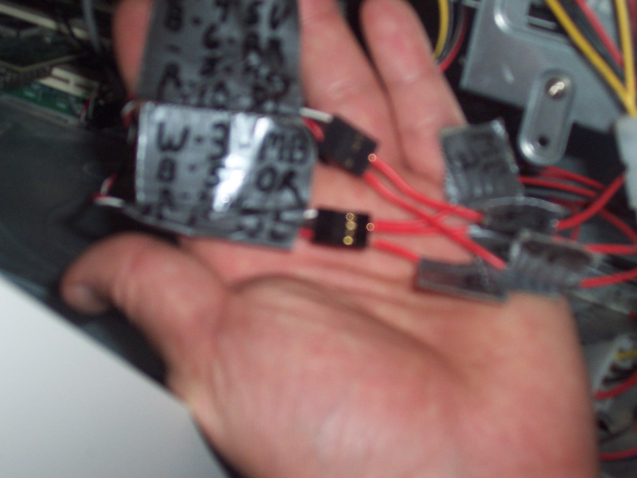
The CDIn audio cables in action:

(Yes, I was one short and that is actually a power supply cable up there between the mic and the ground. And yes the difference in the resistance might be doing some minor weird things to my mic sound quality…)
And the wire with a little soldering…

I labeled every single line with the handy man’s best friend: duct tape, and connected it all up. See how nicely the wires plug in there?
The audio jacks fit nicely, floating above the now reattached FPA connector board.
And the final result, a working Front Panel Audio Connector where there wasn’t one before:
The front speakers turn off when I plug the mic in and microphone works! I would call that a success!
Known Issues:
1. Left and right head phone channels are somehow reversed – this is probably just a labeling problem. I need to double check it and reverse two wires.
2. Microphone quality is bad… However it was also bad on my last sound card. I think it is actually these headphones. I need to borrow someone’s to see if it is an issue with the headphones themselves or if it is electromagnetic interference from the extra fans I put into the case….
I could wrap the wires in foil, wind around that with my abundance of red 22 gauge wire and then wrap that all in duct/electrical tape and produce a highly shielded wire and see if that makes a difference…
Any thoughts?
Nice job, I just built mine yesterday, but do you know of a place that sells the ac97 connector? I don’t like the bang up pinning job I did, I actually soldered wire to jumpers to connect to the pins. I don’t like using the jumpers though and would like to find ap lace to just buy the connector, and I’ll wire to that and plug it in.
Better , use shield wire which is necessary for audio frequencies ( Signal ).